Diagram For Honeywell Pneumatic Economizer Controls Pneumati
Pneumatic frc Honeywell 3 port valve wiring diagram » diagram board Honeywell economizer fundamentals
Air Economizer Fundamentals with Honeywell Home Global Field Devices
Honeywell building controls 4 wire zone valve wiring diagram Everything you need to know about wiring a honeywell actuator valve
Wiring thermostat coil ahu fcu
Honeywell pneumatic damper actuator,30 psi, linear mp909d1201/u, 1Pneumatic controller illinois Introduction to pneumatic control systems: clip 2 of 5Pneumatic controller – human dynamics and controls lab.
Honeywell pressure controllersHow to calibrating a honeywell pneumatic thermostat in a few easy steps Honeywell w7212a1025 economizer controlHow to program honeywell thermostat and lockout diagram হানিওয়েল.

Rheem hvac model numbers
Millivolt gas valve wiring diagramHoneywell engineering manual of automatic control for commercial Fan coil unit full wiring with thermostat and valve actuatorHoneywell gas control valve manual.
Honeywell pneumatic calibration instructionsEconomizer controls Honeywell actuator wiring diagramFrc pneumatic system diagram.

Honeywell valves
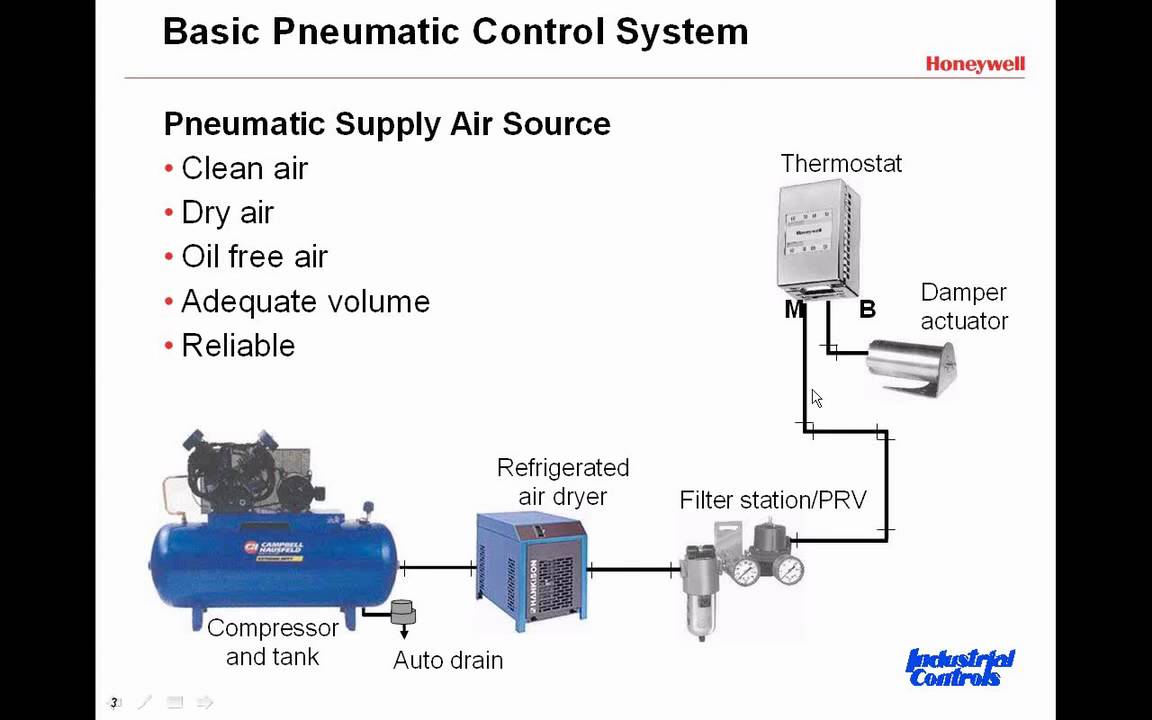
Honeywell pneumatic actuator, direct acting, 4-11#, 3/4" stroke, springSchematic diagram of pneumatic control system Honeywell boiler control manualControls system air basic basics flow refrigeration pneumatic control systems components conditioning introduction used industry.
Air economizer fundamentals with honeywell home global field devicesStanding pilot gas valve wiring diagram Honeywell control valve basic trainingPneumatic thermostats.

Honeywell v8043e zone valve wiring diagram
Honeywell economizer actuator 3 position control signal, 24v, springDraw pneumatic circuit diagram Fcu wiring diagram.
.


Pneumatic Thermostats - Comfort at Your Fingertips - Fireplace Choice
Introduction to Pneumatic Control Systems: Clip 2 of 5 - YouTube

19 Honeywell

Honeywell | PDF | Gases | Valve

4 Wire Zone Valve Wiring Diagram

How to Calibrating a Honeywell Pneumatic Thermostat in a few easy steps

Honeywell Building Controls

Pneumatic Controller – Human Dynamics and Controls Lab